|
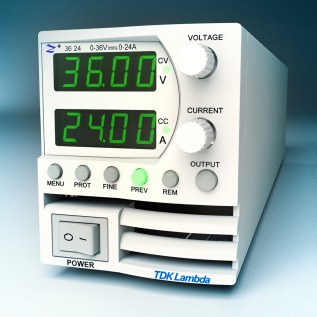
Zxxx-yyy-o-p
где:
xxx
-
максимальное выходное напряжение в пределах от 10 до 100
(см. Номера для заказов - ниже)
yyy
-
максимальный выходной ток пределах от 2 до 40
(см. Номера для заказов - ниже)
o
-
опции (можно
выбирать несколько - см. описание):
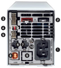
LAN
- сеть
LAN
(и по
умолчанию, т.е. если отсутствует это обозначение
- значит без LAN).
Для стандартного и расширенного корпуса.
IEEE
- GPIB
интерфейс (IEEE 488.2 SCPI (GPIB) Multi-Drop).
Для расширенного корпуса.
IS510
- изолированный
интерфейс для программирования напряжением 0-5V/0-10V (Current
Programming Isolated Analog Interface
.
Для расширенного корпуса.
IS420
- изолированный
интерфейс для программирования током 4-20mA
(Current Programming Isolated Analog Interface).
Для расширенного корпуса.
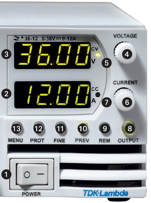
L
- выходные
клеммы на передней панели (Front Panel Output Jacks (60V
or 24A max)
).
Для расширенного корпуса.
p
-
Шнур сетевого питания с
вилкой:
E
- евровилка (и по умолчанию,
т.е. если отсутствует это обозначение)
J -
Japan (Япония)
U -
North America (США)
I - Middle East (Ближний Восток)
Например:
Z10-40
(без LAN)
Z10-40-LAN
(c LAN)
|